
Views: 0 Author: Site Editor Publish Time: 2026-09-15 Origin: Site
Rapid ice accumulation on a cooling unit is a critical hardware warning, not merely a minor nuisance. It immediately compromises temperature stability across your storage facility. It also increases daily energy expenditure and severely threatens inventory integrity. When heavy ice insulates the internal coils, it actively blocks essential thermal transfer. If left unchecked, this physical barrier forces the compressor engine into continuous overdrive. Such extreme strain inevitably leads to premature mechanical failure and massive repair bills.
We have developed a systematic, technician-level diagnostic framework to help you identify the precise root cause of this rapid freezing. You will learn how to assess environmental ingress, test cycle components, and analyze refrigerant pressures. Armed with this knowledge, facility managers and business owners can confidently execute targeted repairs, swap broken parts, or plan comprehensive unit upgrades.
Airflow is the first suspect: Blocked fans or compromised door seals introduce excess ambient humidity, which instantly turns to ice.
Defrost failure requires component isolation: Whether utilizing electric defrosting or water defrosting, failure usually traces back to specific sensors, timers, or heating elements.
Low refrigerant is counterintuitive but critical: A refrigerant leak drops system pressure, causing coil temperatures to plummet below freezing and form ice rapidly.
Evaluate replacement over repair if the unit exhibits chronic coil leaks, severe fin degradation, or relies on obsolete, non-compliant refrigerants.
Ice acts as a powerful thermal insulator. Even a single millimeter of ice significantly degrades the internal heat exchange process. The cooling system relies on exposed aluminum fins to absorb ambient heat from the storage room. When a thick frost blanket covers these fins, the unit loses its ability to pull heat effectively. This loss of efficiency forces the temperature inside the storage space to rise. It compromises food safety standards and ruins sensitive pharmaceuticals quickly.
Restricted air movement across the coils triggers a dangerous chain reaction. The system thermostat detects the rising room temperature. It signals the compressor to keep running. Because the insulated coils cannot absorb heat, the compressor runs non-stop attempting to meet the desired setpoint. This relentless operation leads to severe mechanical overheating. It also causes liquid slugging, where unevaporated liquid refrigerant rushes back into the compressor valves. Compressor death usually follows. Compressors represent the highest capital expenditure in commercial refrigeration setups. Protecting them requires immediate attention to early warning signs.
Frequent manual ice removal severely disrupts daily warehouse operations. Facility teams waste valuable labor hours chipping away ice or forcing manual cycles. This constant maintenance breaks cold chain compliance for highly sensitive goods. Door traffic halts. Forklifts must reroute. You lose money every minute the room remains outside its optimal temperature range. Preventing these disruptions requires a proactive approach to maintenance.
Common Mistake: Facility managers often lower the thermostat setting to compensate for a warming room. This actually accelerates the freezing process and destroys the compressor faster.
Verify the mechanical health of your cold room evaporator fans immediately. You must ensure they run at their full rated RPM. Sluggish or completely dead fans prevent warm ambient air from crossing the cold coils. Without this constant breeze, surface moisture simply freezes in place.
Listen for grinding noises coming from the fan bearings.
Visually inspect the fan blades for cracks or heavy dust accumulation.
Use a digital anemometer to measure the actual discharge velocity.
Ensure the fan delay thermostat activates properly after a heating cycle.
Inspect the physical environment around the unit. Look for debris, dirt, or stray plastic wrap blocking the intake grilles. Inappropriate inventory stacking is a notorious culprit. Warehouse teams frequently push tall pallets right up against the unit. This severely starves the system of return air. We highly recommend painting a bright yellow boundary line on the floor. Maintain at least an 18-inch clearance zone around all cooling equipment at all times.
Continuous ingress of warm, humid air easily overwhelms the moisture removal capacity of the system. This leads directly to flash-freezing on the exposed fins. You must secure the perimeter.
Inspect door gaskets: Look for tears, compressions, or gaps along the rubber seals. Slide a dollar bill behind the closed door gasket. If it pulls out easily, the seal has failed.
Evaluate strip curtains: Ensure PVC strip curtains overlap correctly. Replace torn or missing strips immediately.
Check air curtains: If you use powered air doors, verify the downward air velocity reaches the floor.
Diagnostic logic: Heavy frost forming primarily on the front face of the coil usually indicates a room sealing failure. Airflow carries the ambient humidity straight into the front fins.
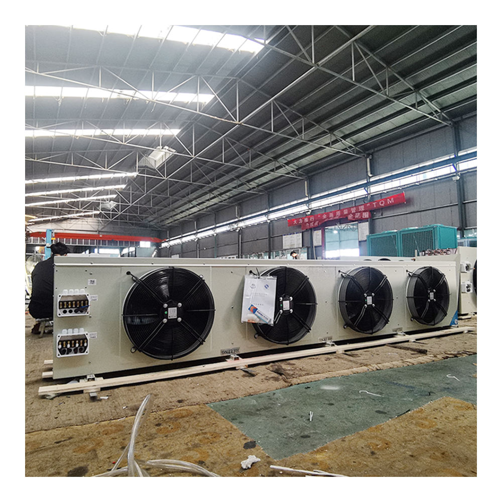
Many modern units rely heavily on internal heating elements to melt accumulated ice. Electric defrosting failures usually trace back to three main components. First, test the internal heater rods for electrical continuity using a standard digital multimeter. Burnt-out rods represent a very common failure point. They remain completely cold while the system thinks it is melting ice.
Second, verify the termination thermostat, commonly called the klixon. This sensor mounts directly to the coil piping. It senses when the ice has melted and shuts off the heaters. If a klixon fails closed, the cycle terminates far too early. The residual ice simply compounds day after day.
Third, check the main mechanical timer or electronic controller. Ensure the programming matches the facility humidity load. If the scheduled duration is too short, the cycle fails to clear the entire coil block.
Some industrial facilities prefer using liquid-based melting methods. Water defrosting systems introduce unique mechanical challenges. You must ensure the internal spray nozzles remain completely clear of hard mineral deposits. Calcium scale clogs these tiny nozzles easily. This creates uneven spray patterns, leaving large sections of the coil completely frozen.
Check the incoming water temperature carefully. It must remain warm enough to melt ice rapidly but not hot enough to generate excess steam. Verify the incoming flow rate matches the strict manufacturer specifications. Low water pressure fails to reach the upper sections of the coil block.
Regardless of your chosen melting method, melted water must exit the room immediately. A clogged or improperly pitched drain line causes serious issues. Melted water pools directly in the metal drain pan. When the cooling cycle restarts, this standing water refreezes instantly. It eventually encapsulates the entire lower half of the coils in solid ice.
Best Practice: Always test your drain lines by pouring a gallon of warm water into the pan. Watch the exit pipe outside the room. If the water drains slowly, snake the line and check the internal drain line heater cable for proper operation.
Many technicians face a common misconception regarding fluid levels. They assume low refrigerant results in warmer internal coils. The laws of thermodynamics dictate the exact opposite. A system leak causes a drastic drop in internal suction pressure. According to pressure-temperature relationships, lower pressure lowers the saturation boiling point of the liquid.
The coil temperature plunges far below normal operating parameters. When the metal surface drops severely below freezing, ambient moisture solidifies upon contact instantly. This creates rapid frost buildup deep inside the fin pack. You cannot fix this with a heater. You must fix the underlying chemical leak.
The thermostatic expansion valve meters the exact flow of liquid into the system. Check this valve for severe restrictions, internal sticking, or general mechanical failure. A starving expansion valve feeds far too little liquid into the piping. This replicates the exact freezing symptoms of a massive system leak. The pressure drops artificially. The coils freeze solid.
Look for frost forming directly on the valve body itself. Check the sensing bulb attachment. It must remain tightly strapped and heavily insulated against the suction line. A loose bulb feeds erratic data to the valve mechanism.
If you suspect a sealed-system pressure issue, you must call a certified HVAC/R technician immediately. They will attach calibrated digital gauges to the service ports. They will verify actual superheat and subcooling metrics. These precise measurements confirm whether the unit requires a simple valve adjustment or a comprehensive leak search and recharge.
Diagnostic Pressure Anomalies Matrix
Observed Symptom | Suction Pressure | Superheat Reading | Probable Root Cause |
|---|---|---|---|
Coil freezing, frost on TXV body | Abnormally Low | High | Starving TXV / Restricted liquid line |
Rapid ice on front fins only | Normal / Slightly High | Normal | Poor room sealing / Humidity ingress |
Solid block of ice, compressor running hot | Abnormally Low | High | Low refrigerant charge / Active leak |
Ice forming only on lower half of coil | Normal | Normal | Clogged drain line / Failed pan heater |
Facility managers eventually face a tough financial decision. Should you fix the broken components or replace the entire unit? Making the wrong choice drains maintenance budgets quickly.
Repairing individual parts makes sense under specific conditions. First, check the age of the equipment. If the unit is under seven years old, it usually has plenty of operational life left. Second, evaluate the specific failure. Failures isolated to easily swappable parts warrant a quick repair. Replacing a single fan motor, swapping a faulty timer board, or installing a new door seal takes minimal time. Third, inspect the core copper and aluminum coil block. If it remains bright, clean, and entirely free of oil spots (which indicate leaks), keep the unit running.
Chronic Refrigerant Leaks: Micro-leaks buried deep inside the coil block are notoriously difficult to braze reliably. They often indicate widespread, systemic metal corrosion. Do not waste money chasing multiple small leaks.
Fin Degradation: Inspect the aluminum fins closely. If they appear heavily oxidized, brittle, or completely flattened, the unit cannot breathe. Heat transfer capacity is permanently lost. You must replace the unit.
Regulatory Compliance: Check the equipment data plate. If your current setup utilizes phased-out refrigerants like R-22 or restricted HFCs, parts will become incredibly expensive. Replacing the unit with a modern, eco-compliant system offers much better long-term financial security.
Technological Shifts: Older units use rigid mechanical timers. They activate heaters even when no ice exists. Upgrading to smart controllers with on-demand sensors can significantly lower your monthly energy bills.
Check basic airflow first: Verify fan speeds and clear away inappropriate inventory blocking the intake grilles. Proper air movement prevents most surface freezing.
Secure the environment: Inspect all door gaskets and strip curtains. Stopping humid air from entering the room drastically reduces the daily moisture load on the system.
Test electrical components systematically: Use a multimeter to isolate failed heating rods, faulty klixons, and bad timers before assuming a major mechanical failure.
Do not ignore low pressure: Remember that low refrigerant causes freezing temperatures inside the coil. Hire a certified professional to check superheat and subcooling metrics.
Evaluate unit age and condition: Stop repairing heavily corroded, leaky coil blocks. Sourcing a modern, highly efficient replacement is the most financially sound decision to protect your operational uptime.
A: Typically, systems require a cycle 3 to 4 times a day, lasting about 20 to 30 minutes each. However, this varies wildly based on daily room usage and internal humidity loads. If you use smart on-demand controllers, the system only activates when it physically detects ice, saving significant energy.
A: No. Using mechanical tools like hammers, screwdrivers, or scrapers risks puncturing the delicate copper refrigerant tubes. This instantly turns a minor icing issue into a catastrophic, expensive system failure. Always use a forced manual mechanical cycle or gently pour warm water to clear severe blockages.
A: Summer brings significantly higher ambient temperatures and heavy humidity. If facility door openings are frequent and your rubber seals are poor, this excessive moisture load easily overwhelms the system. The unit simply cannot remove the humidity fast enough, resulting in rapid condensation and subsequent flash-freezing.


